Conversion Chart

You’d think by now that I had every piece of brass and plastic available. However, for whatever reason, I’ve been holding off and only buying strip brass piecemeal for all these years. This Christmas I finally broke the bank and spent the dough required to get kitted out with at least one of each of Special Shapes’ and KMS’ strips. I’ve got a new way to organize these sorts of things, which involves some recycled cardboard and a Famous Grouse box, and so, I spent a little time putting the strips away.

Along the way, I wound up making another conversion chart for fractions to decimals. I used to have one of these hanging over the workbench, but it’s gone now. They’re a very handy device, and cheap too. So, if you have a printer, you’re welcome to grab this one and hang it over your workbench too. I hope it helps you get faster. I created it on Google docs for easy sharing

Brakes mostly done

Here are the brakes almost completed. This is, I think the first time I’ve used turnbuckles to model the clevises. These are tricky, and I think I’ve decided the best thing to do is to glue them to the rods while they are still on the sprue, then cut them in half. You’d wind up sacrificing half the turnbuckles, but I think I lost that many to the dust bunnies anyway.

The new train desk

It’s been embarrassingly long since I last posted on this blog. The reason? Well, our family started to grow again, and I had to find space for a queen size bed in what used to be called the train room. Needless to say, this entailed a huge disruption to train construction. The train desk used to take up a whole wall of the basement; now, however, all the bookshelves that were along another wall have had to move under the layout to make room for a murphy bed. So the train desk had to move again, and has shrunk from 14′ long to about 6′, including photo studio. You can see the new compact version here.

I’ve had to collapse the photo studio into the middle drawer, and the photo floods have moved into storage (will they ever reappear?). I’m now shooting all digital, including for print, and the daylight compact fluorescents give very good colour reproduction.

I also had to become much more efficient about drawer space. I lost one of those crappy plastic sets of drawers on casters. Good riddance, really. All the tools that were in there have found new homes either in the red tool chest or in the desk drawers. Some tools, like the Dremel, have moved out of drawers altogether, and may even get used from time to time now.

One of the bigger jobs was organizing all the pieces of material that I had squirreled away in boxes. For years, I’ve kept bags of styrene strip stapled to pieces of card in a Famous Grouse Whiskey box. Unfortunately, I never knew what to do with all the pieces of brass wire, strip, tube and such that doesn’t come in bags. Finally, I devised a way to create pockets, and sorted through them all. That was a long and somewhat surprising process; I discovered that I have loads of 3/32″ brass rod, but barely any 1/16″, for example. Finding out what you have is one of the many benefits of getting organized.

I imagine I’ll be shifting things around for a while yet, but at least I can now see the top of the desk again, and could probably put my hands on almost anything in a few minutes of head scratching and a few more minutes of digging. Hopefully the model updates flow a bit better from now on.

Etched trucks – the design process

A reader just asked with regards to my trucks,

“I’m most interested in your design process, how you first determined you could etch the truck sideframes in such a way several folds would complete the process, and then how you engineered the design. I’ll check out your blog and if I’m still confused I’ll email you again.”

To tell the truth, I thought about these trucks for years before coming up with this approach. I tried casting them in resin, but the sections are too small to cast reliably, and who knows what the performance would be like if you could get them to come out of the mold? I really don’t recall how I came up with the idea of etching them, but it was probably from reading too many British magazines.

I think the design probably started with thinking about how to keep the two axle holes the right distance apart. So, I might have started with a plate with the two axle holes etched in, planning to solder the arch bars to this plate, and then file away the excess once everything was solid. From there, it’s not a long way before you realize that the arch bars can also be etched and folded onto the plate accordian style.

The tricky bit, which stumped me for ages, was how to attach them to the bolster. In Proto:87, it is especially useful to have this all square. I toyed around with various ideas involving posts and holes in the bolster, much like some of the equalizing delrin trucks on the market. But, I could never come up with a satisfactory way of isolating the two sides. Finally, I realized that I could use the bolster much as the prototype did.

Once I’d figured it all out in my mind (I inherited very good spatial visualization from my grandfather), I drew it up in QuickCad. I didn’t know exactly how big to make the half-etched gaps for right angle and 180 degree bends, but I surmised that it must be something like the distance around an appropriate arc of radius equal to the 3/4 the thickness of the material. My laser printer only does 600 dpi, and so, that calculation is probably way more accurate than my laser printer is able to resolve anyway. It happens that the folds do come out crisply, so I guess I wasn’t too far wrong.

I then scaled up the design I forget how many times, and transfered the design to foam core for testing. I scaled it up sufficiently so the foam core was the right thickness to represent the final metal. This foam core mockup rattled around my basement for ages, but it seems to be gone now, otherwise I would show it to you. The mockup worked, and so, I started working in actual metal.

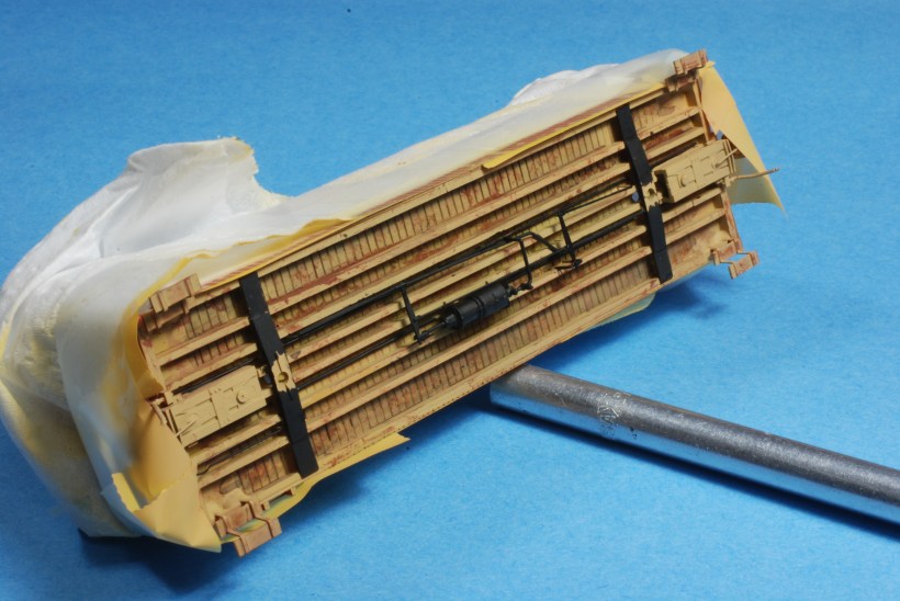
Now that I’ve assembled two pairs of trucks, I plan to completely revise the design before I make any more. The original design called for a half-etched bottom chord, which turned out to be too flimsy due to my unpredictable etching process. On the second iteration, I therefore changed the design to make the bottom chord full thickness; this was not a complete revision, and it turned out less satisfactory. The other failing is that the top two arch bars are only connected to one another at one end. This is a result of them being slightly different shapes. However, the difference is not noticeable at all, and so, I think I will connect them at both ends, and dramatically simplify the soldering process.

The rest, as they say, is history. Except in this case, it really is history because I’ve written much of it down somewhere.

Russia Iron

Someone recently asked for my Russia Iron recipe. I thought I would find it in the scratch steam yahoo list, where I thought I described it, but apparently I never did. So here is how I made mine for my 4-4-0. I apologize in advance for the lack of science, or even repeatability.

I first painted the jacket silver. Actually, Poly Scale Stainless Steel, but I don’t imagine the exact species of silver matters too much. If I recall, I gave this a little buffing before the next coats. The next coat was a 1:3 glaze of D&H Avon Blue, which is a nice bright blue (again, I don’t imagine the species matters too much), in gloss. Glazes are tricky, especially if your airbrush wants to clog like mine did, and you have to know when to stop. I stopped when the colour was sort of a sky blue, so I could still see silver through the blue. Finally, I over-sprayed that with a 1:3 glaze of engine black, and I stopped that when I felt it looked good.

Caboose underframe

This might be the last styrene underframe I ever do. There are two reasons: first they didn’t actually paint underframes, even on passenger cars. Second, making styrene look like wood is a nuisance, but making wood look like wood is a doddle. So the next project is going to try a wooden underframe again, and I’ll paint all the hardware before installation rather than after so I don’t have to deal with that either.

Even so, I think this is turning out reasonably well. You’ll have to wait until the lettering goes on to see the sides.

Coupler quandary

I am finding myself in a little quandary on the subject of couplers. You see, looking into my collection of stock, I find I have everything from Kadee #5s, to Kadee 711s, Kadee N-Scale (all built before the scale coupler craze), and Accumates. I tried the Sergents; many people like them and I suggest that everyone should try them, but they were a little too hands-on for me.

So, I was all ready to put Accumates on the new caboose, but on the test fit, I thought, “gee, they look a little big.” Of course, we all know that couplers got bigger (I don’t recall when, do you?), and this is most likely the reason they look oversize. So, then I went through my reference material to see if I could find out how much too big they are. I only found one dimension: 13.5 inches from end beam to coupler face. The Accumates are about 19 scale inches, and even the N scale are 17 scale inches (but a good deal lower in profile). Now, I just don’t know what to do.

Does anyone have any real information on the size of the early MCB couplers that might help me make this decision for once and for all? I’d love to standardize before I find myself with too many more models to change.

Caboose coming along

As promised, here is the caboose body as of today. I’ve installed the cupola windows, and I guess I will paint the interior of the cupola before roofing it over. I still need to figure out how to take photos with the new camera. I suspect I may be able to cheat and use the daylight flourescents instead of the tungsten photofloods. This would be cool because I might then be able to get rid of the photo studio.

CAoRM Victoria and Caboose Update

Last weekend (Victoria Day weekend) was the Canadian Association of Railway Modellers’ (www.caorm.org) annual national convention. This year, Victoria played host on the University of Victoria campus. For a Canuck like me, and especially as a BCer, there was a lot to choose from in the program. I attended some excellent workshops on topics such as the Dolly Varden Mines Railway (an old fave), mining in the Boundary District of BC, Mines in general, PGE modelling and scratchbuilding locomotives in brass.  Overall, there was more going on than anyone could hope to take in; thank goodness I registered so late, all the tours were sold out.

I delivered two clinics: one on scratchbuilding and another on Proto:87. Each was attended by about 30 people. I had the most fun with the scratchbuilding clinic, which covered much of the material from my mini-series of articles in Railroad Model Craftsman (RMC). For this clinic, I prepared some basic powerpoint, but spent the bulk of the time demonstrating through a live video feed. It’s alway fun to see people start to understand my techniques, which revolve mostly around getting value out of each measurement you make.

The P87 clinic was about recent advances in Proto:87, and covered many of Andy Reichert’s excellent products (see www.proto87.com). This clinic was more straightforward, being mostly powerpoint and questions. How did we ever do clinics before Powerpoint?

For the show, I managed to do quite a bit of work on the caboose. Sadly, my camera is eating batteries too quickly these days, and so, for the sake of the environment, I have no pictures. Suffice it to say that the body is all but complete, as are the end railings. I had rushed the cupola so I could show it at my clinic, but I made a bit of a bodge of it, so I re-did it. Now it looks pretty good, or at least sufficiently good for me. I’m about to install the windows, then I’m down to detailing out the underframe and painting.

I’m working on buying a digital SLR with the proceeds from my articles in RMC, and once that’s in play, I’ll get some more pics up to share with you. I wonder how many of you there are, anyway?