The new train desk

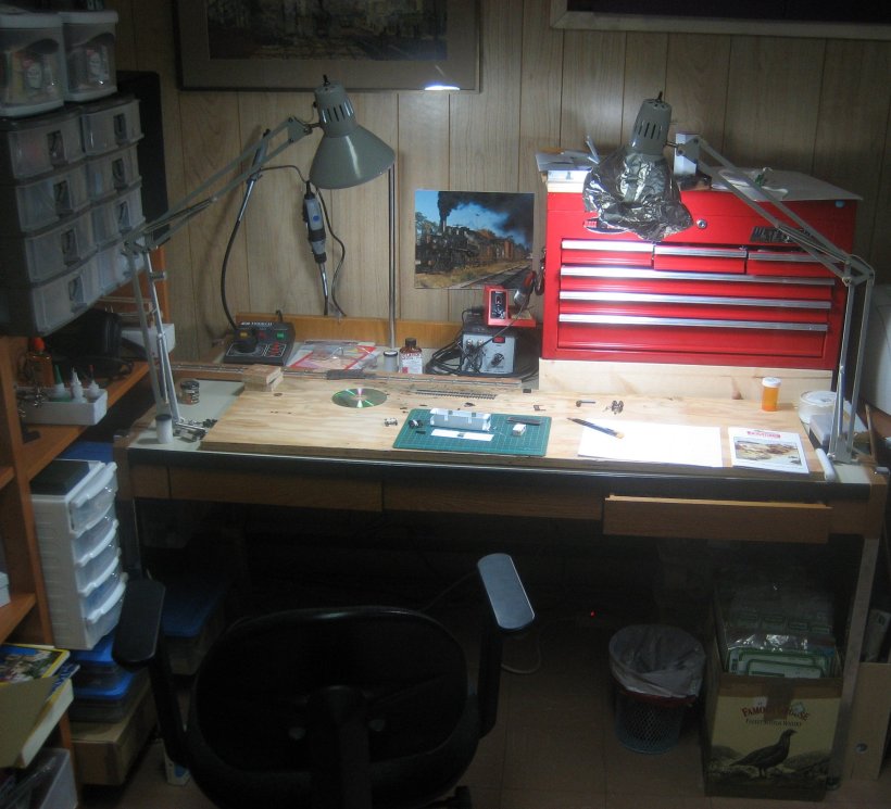
It’s been embarrassingly long since I last posted on this blog. The reason? Well, our family started to grow again, and I had to find space for a queen size bed in what used to be called the train room. Needless to say, this entailed a huge disruption to train construction. The train desk used to take up a whole wall of the basement; now, however, all the bookshelves that were along another wall have had to move under the layout to make room for a murphy bed. So the train desk had to move again, and has shrunk from 14′ long to about 6′, including photo studio. You can see the new compact version here.

I’ve had to collapse the photo studio into the middle drawer, and the photo floods have moved into storage (will they ever reappear?). I’m now shooting all digital, including for print, and the daylight compact fluorescents give very good colour reproduction.

I also had to become much more efficient about drawer space. I lost one of those crappy plastic sets of drawers on casters. Good riddance, really. All the tools that were in there have found new homes either in the red tool chest or in the desk drawers. Some tools, like the Dremel, have moved out of drawers altogether, and may even get used from time to time now.

One of the bigger jobs was organizing all the pieces of material that I had squirreled away in boxes. For years, I’ve kept bags of styrene strip stapled to pieces of card in a Famous Grouse Whiskey box. Unfortunately, I never knew what to do with all the pieces of brass wire, strip, tube and such that doesn’t come in bags. Finally, I devised a way to create pockets, and sorted through them all. That was a long and somewhat surprising process; I discovered that I have loads of 3/32″ brass rod, but barely any 1/16″, for example. Finding out what you have is one of the many benefits of getting organized.

I imagine I’ll be shifting things around for a while yet, but at least I can now see the top of the desk again, and could probably put my hands on almost anything in a few minutes of head scratching and a few more minutes of digging. Hopefully the model updates flow a bit better from now on.

Etched trucks – the design process

A reader just asked with regards to my trucks,

“I’m most interested in your design process, how you first determined you could etch the truck sideframes in such a way several folds would complete the process, and then how you engineered the design. I’ll check out your blog and if I’m still confused I’ll email you again.”

To tell the truth, I thought about these trucks for years before coming up with this approach. I tried casting them in resin, but the sections are too small to cast reliably, and who knows what the performance would be like if you could get them to come out of the mold? I really don’t recall how I came up with the idea of etching them, but it was probably from reading too many British magazines.

I think the design probably started with thinking about how to keep the two axle holes the right distance apart. So, I might have started with a plate with the two axle holes etched in, planning to solder the arch bars to this plate, and then file away the excess once everything was solid. From there, it’s not a long way before you realize that the arch bars can also be etched and folded onto the plate accordian style.

The tricky bit, which stumped me for ages, was how to attach them to the bolster. In Proto:87, it is especially useful to have this all square. I toyed around with various ideas involving posts and holes in the bolster, much like some of the equalizing delrin trucks on the market. But, I could never come up with a satisfactory way of isolating the two sides. Finally, I realized that I could use the bolster much as the prototype did.

Once I’d figured it all out in my mind (I inherited very good spatial visualization from my grandfather), I drew it up in QuickCad. I didn’t know exactly how big to make the half-etched gaps for right angle and 180 degree bends, but I surmised that it must be something like the distance around an appropriate arc of radius equal to the 3/4 the thickness of the material. My laser printer only does 600 dpi, and so, that calculation is probably way more accurate than my laser printer is able to resolve anyway. It happens that the folds do come out crisply, so I guess I wasn’t too far wrong.

I then scaled up the design I forget how many times, and transfered the design to foam core for testing. I scaled it up sufficiently so the foam core was the right thickness to represent the final metal. This foam core mockup rattled around my basement for ages, but it seems to be gone now, otherwise I would show it to you. The mockup worked, and so, I started working in actual metal.

Now that I’ve assembled two pairs of trucks, I plan to completely revise the design before I make any more. The original design called for a half-etched bottom chord, which turned out to be too flimsy due to my unpredictable etching process. On the second iteration, I therefore changed the design to make the bottom chord full thickness; this was not a complete revision, and it turned out less satisfactory. The other failing is that the top two arch bars are only connected to one another at one end. This is a result of them being slightly different shapes. However, the difference is not noticeable at all, and so, I think I will connect them at both ends, and dramatically simplify the soldering process.

The rest, as they say, is history. Except in this case, it really is history because I’ve written much of it down somewhere.

Caboose underframe

This might be the last styrene underframe I ever do. There are two reasons: first they didn’t actually paint underframes, even on passenger cars. Second, making styrene look like wood is a nuisance, but making wood look like wood is a doddle. So the next project is going to try a wooden underframe again, and I’ll paint all the hardware before installation rather than after so I don’t have to deal with that either.

Even so, I think this is turning out reasonably well. You’ll have to wait until the lettering goes on to see the sides.

Coupler quandary

I am finding myself in a little quandary on the subject of couplers. You see, looking into my collection of stock, I find I have everything from Kadee #5s, to Kadee 711s, Kadee N-Scale (all built before the scale coupler craze), and Accumates. I tried the Sergents; many people like them and I suggest that everyone should try them, but they were a little too hands-on for me.

So, I was all ready to put Accumates on the new caboose, but on the test fit, I thought, “gee, they look a little big.” Of course, we all know that couplers got bigger (I don’t recall when, do you?), and this is most likely the reason they look oversize. So, then I went through my reference material to see if I could find out how much too big they are. I only found one dimension: 13.5 inches from end beam to coupler face. The Accumates are about 19 scale inches, and even the N scale are 17 scale inches (but a good deal lower in profile). Now, I just don’t know what to do.

Does anyone have any real information on the size of the early MCB couplers that might help me make this decision for once and for all? I’d love to standardize before I find myself with too many more models to change.

Caboose coming along

As promised, here is the caboose body as of today. I’ve installed the cupola windows, and I guess I will paint the interior of the cupola before roofing it over. I still need to figure out how to take photos with the new camera. I suspect I may be able to cheat and use the daylight flourescents instead of the tungsten photofloods. This would be cool because I might then be able to get rid of the photo studio.

Caboose body coming together

Here are the walls, floor and roof of the body coming together. The ends are .020″, perhaps against my better judgement. The roof and walls are .040″, and the floor is more scribed .020″ styrene.

It’s always fun to see a model suddenly leap off the page like this. Next step is to trim and do the underframe. I thought for a long time about the frame, and finally wound up deciding to build it in place. This may be an error. I’ll let you know when I’m done.

Caboose trucks

The Canada Atlantic’s trucks were for the most part swing motion. Even the cars made by Pullman came with a swing motion truck. As far as I know the only ones with a standard archbar were the 6000 box cars.

Here I’ve assembled the main parts of the bolsters. There is another layer representing the swinging, spring plank to go, and that will get the round holes. On the locomotive, I bodged together brakes that hung below, and never worked satisfactorily. This time, I’m going to hook them onto the bolster above the wheels. We’ll see how that works.

Looks like it’s time to fire up the casting process to make all those journals. Perhaps this time, I’ll cast the brake shoes as well. They were a nuisance to make last time.

Truck sideframes under development

Here are the truck sideframes. The Canada Atlantic used these swing motion trucks much later than other railroads. Because I am modelling in Proto:87, and most trucks would want modification anyway, I’m etching them.

Each sideframe starts as a single piece of metal, which I bend 18 times then solder together. They are self-jigged to come out reasonably accurately. Unfortunately, I changed the design ever so slightly – by making the bottom chord full-thickness instead of half – and now the design doesn’t work so well anymore. Three sideframes turned out okay, but the fourth was a disaster; so I am running another eight to the original pattern now.

When I go to redo the design again, I’m going to make it so the upper diamond is connected at both ends since this is the hardest part to pull off. I think I’ll also give the slot into which that tab fits a little more space so it has a chance to etch through. If I could figure out a better approach for the two fingers that line up with the bolster, I would, as well.

Incidentally, my company just launched a new family social networking site, kinzin.com. It’s got nothing to do with trains, but maybe you’d like to check it out anyway.

Etchings for caboose

What a nuisance! I don’t recall having so much trouble with Press n Peel Blue etching resist when I did the trucks for my locomotive. Of course, reading back over those posts, I see that I used up five sheets of the stuff before I got one I was happy with. So, perhaps the memory is clouded with time.

As before, I checked in on Ron Hilsden’s page, and more or less followed his excellent instructions, minus the rock tumbler and the microwave. The key that I had forgotten was to sand the brass so it has a little tooth for the toner to stick to. Hopefully I’ll remember that next time. Other things to remember:

  • Make sure the printer cools down between pages, otherwise the PnP wraps around and jams inside.
  • Aim for smaller etchings. My printer (an HP 1200) varies by as much as .030″ over the length of a page. Best, then to have the two sides near to each other.
  • Use Ron’s tip of the .020″ dots to help line up the two sides
  • Sand the brass before printing to give a little tooth for the toner to bind to – bears repeating!
  • Let it cool completely before peeling off the backing

From left to right on the fret here, there are the end doors, the trucks (19 folds for each frame), the side windows, the cupola windows, and the steps. I toyed with the idea of etching the cupola itself, but decided it was easy enough to make from scratch.